|
To start making the plug for our custom head light housing we first started with
laying a piece of plastic on top of the bumper. Its purpose was to prevent in sticking of
the initial plaster junk that will be laid when making the housing. A partial
spare piece of fenders where treated same way around the light housing openings
and under where it mounts and extending where possible plaster could expand to.
Mounting surface for the projectors where then attached to the bumpers in place
learned from other versions of the housings to give enough clearance for the
projectors to the lens covers but more to give enough clearance to the wheel
well lining. some pictures of the process can be seen in the
gallery. The fenders where fastened to the chassis as it would when
finished. With the initial prep work completed we started on laying some
plaster. All of the little small chambers and spaces where forced with as much
plaster as possible so that it will provide some sort of locating reference when
the housings are removed and placed back during contouring process.
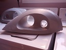
Main housing
The main frame of the headlight is what holds everything together and parts
mounted onto it.
The
concept of it is to have a frame that with a help of mounting plates which are
used for aligning the projectors and to mount projectors to and them the plates
mounted onto the headlight frame. A version of the frame will have small
projectors embedded into the surrounding as accent within which LEDs are
mounted. Orange LED's on the side are for turn signal and forward facing white
LEDs are used as accent for daytime driving lights.
With opening for the projectors a trim ring/plate is mounted into the opening
which then is covered with a lens protecting the projectors from debris and
water. Cause of the type of projectors used in the headlights, back side
has cover shell mounted to it that is dust and water tight sealed with openings
to access light bulbs incase one burns out and a mounting surface for HID driver
Trim ring (s)
To make the headlight look "finished", trim rings are fabricated and
mounted on top of the frame projector opening. It has additional embedded
forward facing LED projectors for turn signal indicators.
Back cover
To protect bulbs and in general keep the projectors clean from any dust or
water. The back of the headlight will be covered with a back cover clam shell
that will act as support to the main frame and at the same time protecting the
projectors.
Cover lens
As the shape of the headlight is kind of tear dropped and want it to be durable
to withstand hits of small rocks. Lexan or polycarbonate is probably the only
material that can withstand the impact from road debris. Ideal way to make it
would be to have it injection molded. However as this is cost effective
alternative is to vacuum form it from a flat sheet.
Making the main headlight housing plug version 3
Main plug
Started with set of HID projectors that we chose for the headlights, one
Bi-Xenon main projector for Low and High beams for driving at night and a
smaller projectors as fog lights as they had been designed with short wide range
just to be a fog lights however most likely will replace the original H3
filament type bulb with LED. Decision is still out as might use them as driving
lights provided bumper fog lights will be made. An bi-color amber-white LED will
fill in a trim around the housing making dual purpose marker / turn signal
indicator
With very short area in front of the wheel, had to figure out placing of the
projectors in a way that they would be as far out to the sides as possible and
still provide enough clearance to the wheel without hitting it and having enough
room for wheel well so that the wheel would not be hitting the housing.
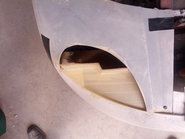 After
finding out the spot for each projector and marking a position, After
finding out the spot for each projector and marking a position,
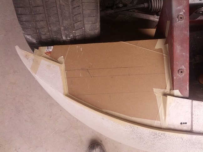 cardboard
was used taped onto the bumper to make extension to the pumper so that
the body of the housing can be made. cardboard
was used taped onto the bumper to make extension to the pumper so that
the body of the housing can be made.
With the mounting face of each projectors marked on the cardboard we them
fastened a vertical piece of additional piece of cardboard and covered it with masking tape
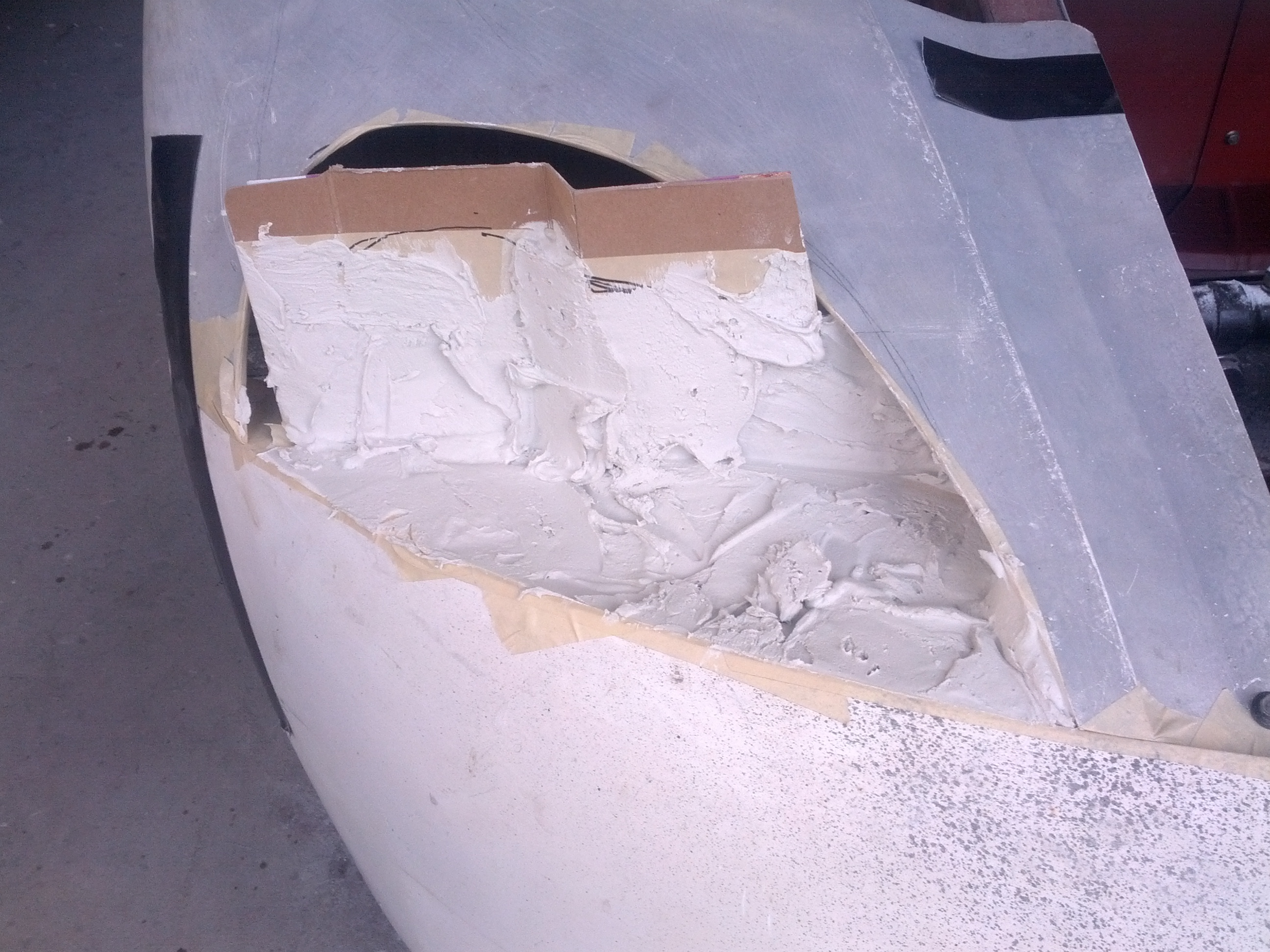
which will peal off after the plaster is cured. With a very short piece of the
fender and estimated headlight size cutout from it and taped back side it was
fastened to the chassis. More tape was used to provide barrier between
chassis, fender section and bottom cardboard and filled any holes. The cavity
was filled with plaster and allowed to dry. It took 3 fillings to build up sufficiently and have enough
thickness and mass for the main housing so that it could be pulled out with out cracking
it.
and mass for the main housing so that it could be pulled out with out cracking
it.
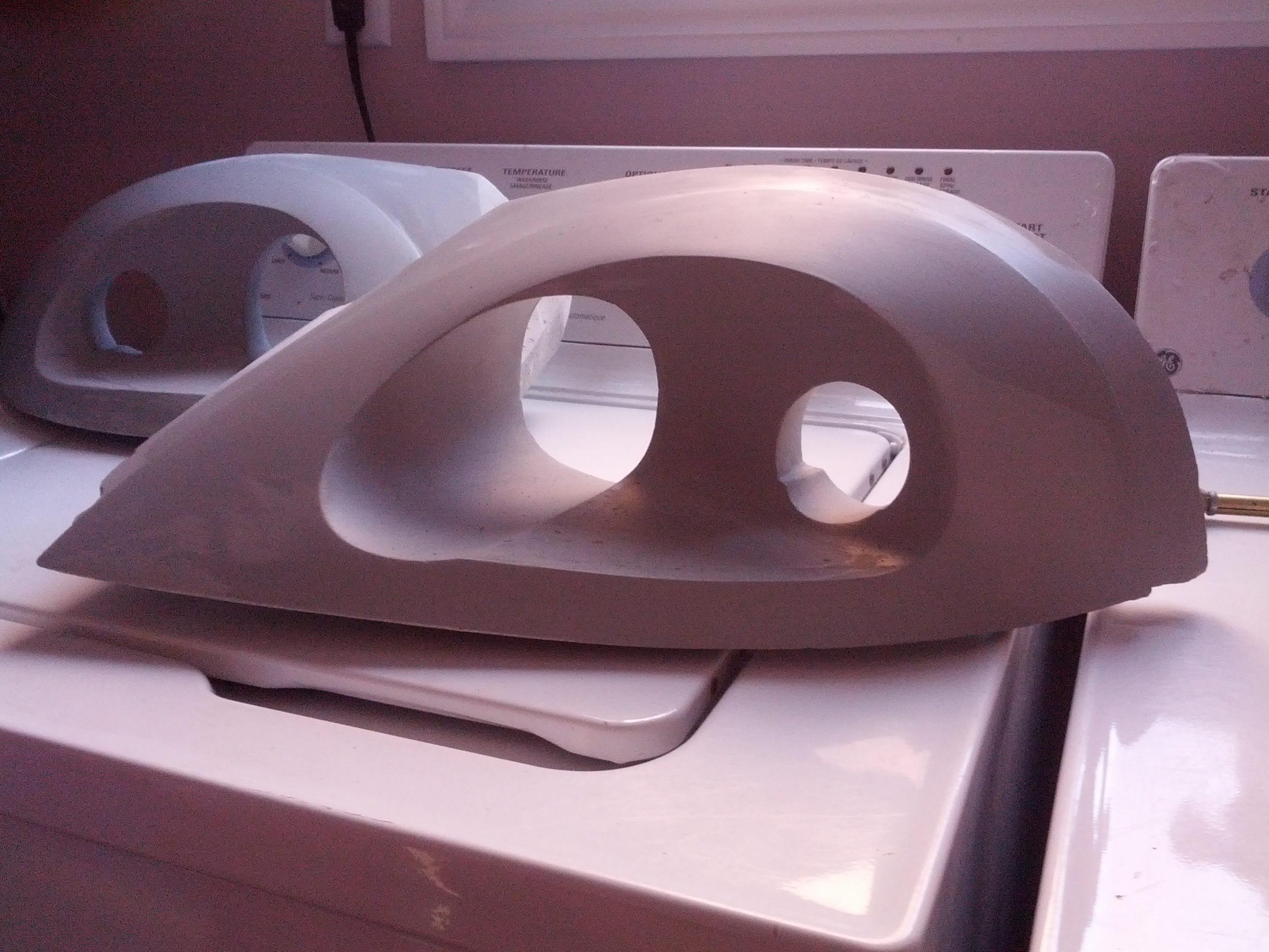
Material used for the projector where peeled off and using straight edge, the
plaster was marked to surface of the fender and the vertical part of the plaster
was trimmed to rough shape. While still relatively soft, front fascia was carved
revealing starting shape shape of the headlight
After making mounting plate for the projectors and positioning on the mounting
surface on the housings, holes where carved out so that the projectors could fit
in and more contouring was done. With the headlights bit lower then version 2
and main projectors sunk bit lower, a bottom plate had to be made to compensate
for the projectors sitting lower and the cavity going lower then original plug.
Further adjustments tot he front and projector cavity was done, however one
thing that was missing was the the upper extension as to where the fender would
be mating and provide ledge for it to sit on and to have some good aesthetic
appearance. To correct that an extension was added to the back by making sudo
overhang over the projectors. To make that, a piece of cardboard was attached
covered with nonstick water resistant tape. From the bottom plaster was applied
and as it dried the cardboard was pulled off revealing the overhang. This
allowed not just an area for the fender to sit on but also space for some
attractive visual look. Problem with it was the curvature and thickness as to
that it would not be to big but substantial and look good.
Adjustments to the curvature and symmetry continued.
 At
some point it was discovered that the extra added thickness on bottom of the
housing interfered with the bumper. It could had been resolved on couple of
different ways however an decision was made to alter the bumper. This does
create a re-do to the bumper. however some work was needed to be done to
facilitate mounting of fender to it so this could be an option to fix that but
also make some sort of mounting for the housings and also to lower the
projectors thus lowering position of them with in the fender as the fender
needed to be altered considerably to hide the headlights and have more smoother
flow. At
some point it was discovered that the extra added thickness on bottom of the
housing interfered with the bumper. It could had been resolved on couple of
different ways however an decision was made to alter the bumper. This does
create a re-do to the bumper. however some work was needed to be done to
facilitate mounting of fender to it so this could be an option to fix that but
also make some sort of mounting for the housings and also to lower the
projectors thus lowering position of them with in the fender as the fender
needed to be altered considerably to hide the headlights and have more smoother
flow.
Re-leave was cut into the bumper effectively lowing the housing an inch. Side
effect of it was that the housings now needed some alteration to the front
contour.
With the bumper location finalized, further alterations to upper curvature and
front trim area was being made and how to add marker and turn lights into the
housing.
As plugs of back dust covers where made the main housings where left alone for a
while. Coming back to it more changes where made to further clearance the
housing from the wheel and provide further clearance to the fender. Front of the
housing where further adjusted around main projector as to ease reflection and
allow wider beam from the projector by cutting out some of the side around the
projector. This also narrowed the decorative band around the housing. Still not
satisfied how to add marker and turn signal light, idea of adding a small band
around the outer rim of the lens was added. This raised the main lens by 1/8
inch but it also allowed space to add second tinted lens for the marker / turn
signal, unfortunately it did not fixed the problem of how to add light to the
ring, so a decision was made to make a continuous cavity with a very narrow
ledge for the lens to be mounted and resting on. The idea of the trench though
might be a very simple one but it allows flexibility of the lights to be mounted
in and a surface mounted led's will work great and still have the ability to
have focusing collimators.
Two last minute alterations to the plug was to bit further rave into in front of
projectors
_5.jpg) side
wall to further thin down on the trim ring and a flat front bottom. The dipped
curved front area in front of the main projector was just not as smooth looking
hence lowering all the way across to edge of the outer raised edge. side
wall to further thin down on the trim ring and a flat front bottom. The dipped
curved front area in front of the main projector was just not as smooth looking
hence lowering all the way across to edge of the outer raised edge.
For more pictures, please look at the
headlight
gallery
.
Dust cover
To make the dust cover it was necessary to establish depth of projectors
allowing clearance for connectors. Having the mounting plates for the projectors
made earlier as part of making the main housing. The projectors where mounted
including bulbs and wire connectors onto the main housing plug as and back was
covered with some paper napkins to cushion against any possible hits and then
covered with plastic sheet sheet guarding against dust while making the cover.
Front glass of the projectors was also protect in similar way for the
projectors. Once satisfied that the projectors will not get damaged, edges of
the main housing where covered with paper and tape so that the rough dust cover
could easily be pulled of from the main housing and not causing any damage to
it. Plaster was spread on back side of the housing covering the projectors and
connectors for the bulbs along edges giving a ridge to that it could be used
later as bonding surface to the main housing.
........more to come
Projector trim
With a recessed face, bare exposed projectors frames the face of the
hadlight does not look very attractive. To cover up the ugliness a cover sudo
trim is made to cover all of the framework behind it.
Now that the version 3 of HID lights had been officially canceled, the
trim is no longer in progress. See revision B of the
lights
Marker lights
As the marker lights will utilize LED's for the light source and to provide some
flexibility into arengment of the LED it was decided that by simply providing
cavity for mounting a circuit board the background lighting can have number of
options. An additional lens will be placed on top to cover up the circuit board
and to diffuse the light and cover the cavity or the cavity can be left empty
all together.
Lens cover
Since we never got to this point, see revision B or
ver
4 of the lights on how they where made
The Mold
Not having a good experience making brake splitter, was bit hesitant on
using regular silicone. However it was the necessary evil that needed to be used
of the amount that needed to be used and expense of it
_07.jpg) due
to the size of the plugs. The silicone mold is needed because of the different
surfaces and contours on the front of the housing where it would be very
difficult to make rigid molds, so with the use of silicone will allow removal
of the mold from the part very easily. A hard shell over it will prevent the
soft silicone keep its shape. This will make major part of the mold with second
part being bottom and back side. Unfortunately the part will need to be made out
of 2 pieces and bonded together later on. due
to the size of the plugs. The silicone mold is needed because of the different
surfaces and contours on the front of the housing where it would be very
difficult to make rigid molds, so with the use of silicone will allow removal
of the mold from the part very easily. A hard shell over it will prevent the
soft silicone keep its shape. This will make major part of the mold with second
part being bottom and back side. Unfortunately the part will need to be made out
of 2 pieces and bonded together later on.
_5.jpg) The
process started as normal finding parting lines between the mold parts. A
cardboard flange was made and taped to the plug. As normal it was waxed and a
single coat of PVA was applied to it for easier separation of the mold from the
plug. Needing the silicone to have substantial thickness do to different curves
and cavities, however to accelerate the curing of the regular silicone, first
layer was applied fairly thin so that not only would cure fasted but also to
spread it into every corner avoiding of making air packets limiting first later
to no more then 1/4 of an inch or less. Enough to cover the surface and thick
enough as not to have any breaks in the layer of silicone. The
process started as normal finding parting lines between the mold parts. A
cardboard flange was made and taped to the plug. As normal it was waxed and a
single coat of PVA was applied to it for easier separation of the mold from the
plug. Needing the silicone to have substantial thickness do to different curves
and cavities, however to accelerate the curing of the regular silicone, first
layer was applied fairly thin so that not only would cure fasted but also to
spread it into every corner avoiding of making air packets limiting first later
to no more then 1/4 of an inch or less. Enough to cover the surface and thick
enough as not to have any breaks in the layer of silicone.
As the silicone cured secondary layers of silicone where applied. Initially
building thickness of the walls and filling in cavities for marker lights and
around projectors as fiberglass filling most likely will not be made for that
section.
The main idea of building up the silicone was to have final smooth surfaces with
out any nibbles sticking out and edges that would easily slip on to the hard
fiberglass shell. After 3 layers the LED trim and projector cavity were
filled and having substantial thickness.
.........more to come
Headlights version 3 Revision "B"
Not quite revision B but more like version 3 B as they are made from
scratch. However since they are more or less a remake of version 3 but with
different geometry and hopefully will follow same opening as the LED aka Version
4.
Couple differences will be in the depth where the projectors are mounted and
rear opening aka dusk cover.
Main plug
.........more to come
Making version 4 of main LED headlight housing plug
The plug
Decided to use F150 led projectors and are physically much smaller then the
HID projectors. They are much shorter and lower though the width remains about
the same as the main HID projector. Being lower height it meant that they could
be pushed forward thus making a larger clearance in weal well. As not to make to
different bumper and mountings. It was decided to re-use bottom plate of version
3 but change mounting and profile of the headlight. Unfortunately, the fenders
need to have different opening for the housings.
.........more to come
|

.jpg)