|
Welcome to myChimaera.com |
||
   |
|
|
Rear lights With the 2 options for tail lights housing need to be different with regular
bulbs there needs to be divider at least for reverse and marker lights and a
separate division for night/brake lights with recesses for light bulb mounts
plus enough clearance for wire harness. Since decision was made to use LED
version, the housing has simple back with a small recess for wire grummet or a
connector. Inside, flange is required for mounting LED panel and a lens on top.
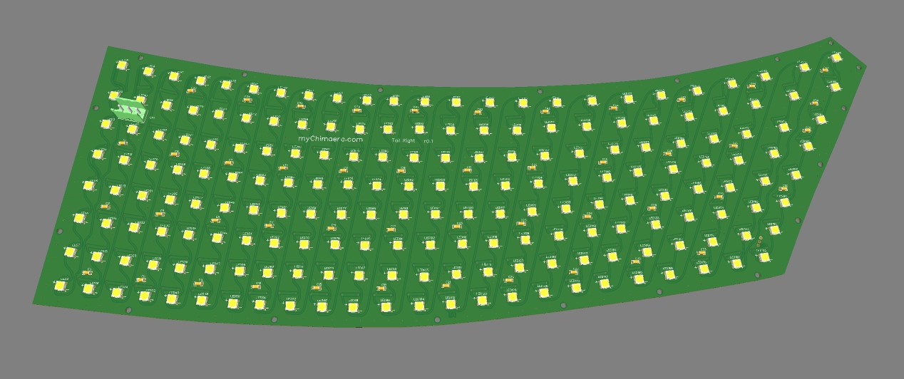
A decision needed to be made with respect to the LED pcb as its quite large
being 485x188mm. A thought was to have it divided 3 pieces , problem with that
was that it needed to be mounted on compound plane so most probable they would
never bend at same rate and would never align so decision was made to make a
single board. It will be much easier to fasten and there would not be any
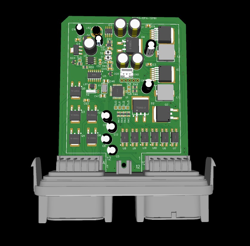
interconnection problems between the 3 boards. The other Now that we are going with LED panel and to control it we need some sort of
processor. Original though was to put it inside the housing be directly
connected to the LED panel and just have necessary left or right turn signals
routed to it. However if configured over CAN bus it would need to differntiate
which side it would be on. Than can be easily resolved with dedicated left or
right port. However to make it more universal it was decided to have it located
external to the light housing as a pluggable module between body harness and
have sub harness going to the light housings. Having it external we can make it
universal controlling both left and light lights. With the Honda/Acura light
stalk it being CAN enabled we can have the module listen to body CAN thus
reducing number wires going to it. However to make it really universal the
controller also has all of the rear light signal inputs. On top of that if we
are listening to just CAN bus the controller decodes and outputs to individual
bulb filament. |
|
| All content is copyrighted 2014 | |