|
Welcome to myChimaera.com |
||
|
|
|
|
Front Brake Splitter. Debating about adding illumination into the splitter and still might just leave the splitter as solid casting though with headlights surface area is rather small and it does not have the real estate for additional light fixture aside of making trim ring act as turn signal / Day Time Running lights (DTR) may not be permissible. So the splitter light can be the way out. And with headlight housing, there is enough space to insert side marker / turn lights. The splitter main part is roughly 13 inches long and 5/8 inches thick so inserting lights into that thin of trim possesses rather some difficulty. The solution to it is LED lights, there is large number of LED sizes with mounting 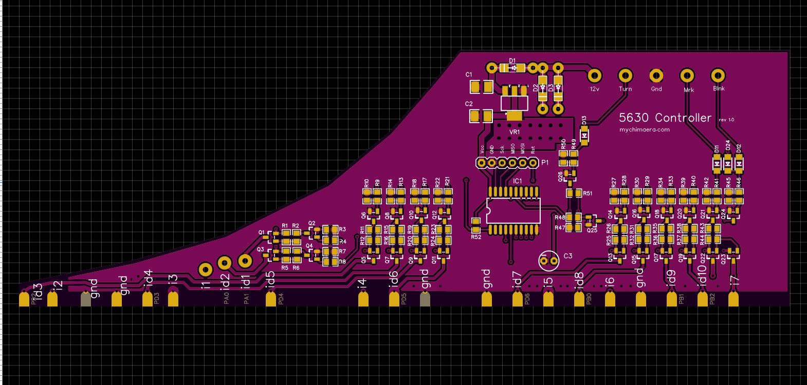 use
regular turn signal for amber LED's. However the LED's need to be mounted on
circuit board as there is barely enough depth for a surface mounted LED's and the
PCB is only 10mm tall and 30cm long. So in order to interface those LED's into
the turn and marker circuits and not to mention that the LED PCB needs to be
mounted in some way, A perpendicular board soldered to back side will be used as
the means for mounting and interface. After some consideration it was decided to
make a microcontroller control of the LED's with some animation as option and
with out it it will just turn all amber LED's with the turn signal. use
regular turn signal for amber LED's. However the LED's need to be mounted on
circuit board as there is barely enough depth for a surface mounted LED's and the
PCB is only 10mm tall and 30cm long. So in order to interface those LED's into
the turn and marker circuits and not to mention that the LED PCB needs to be
mounted in some way, A perpendicular board soldered to back side will be used as
the means for mounting and interface. After some consideration it was decided to
make a microcontroller control of the LED's with some animation as option and
with out it it will just turn all amber LED's with the turn signal. Naturally the front face will be replaced with clear lens in place of the solid part of the housing and underneed will be LED PCB board soldered to control board as its the only way of packaging it all into the enclosure. The LED board is 12 inches long and .4 inches tall. Control Board The microcontroller on the control board is very basic and runs a very simple program to monitor for turning sygnal shutting off white marker LED's and sequencing amber turn LED's Please check the galleries for initial prototype pictures
We had started with prototyping Vero board to hand build our test circuit. Building it by hand though it may take longer to build but we can debug it quicker and correct any possible hardware problems. Since our display will have full RGB LED's to reduce wiring and avoid possible mistakes we had chosen to go with 3 8x8 RGB matrix displays. The RGB leads from the 3 displays are wired in rows and will be driven by octet drivers one per color. The columns are driven by individual transistors grouped into 8 giving us 3 groups. Rather then conventional Johnson counters we felt that using octet latches will give us more flexibility in programming and controlling options for the display. The judgment is still out on that. Please check the galleries for initial prototypes
|
|
| All content is copyrighted 2014 | |