|
Welcome to myChimaera.com |
||
|
|
|
|
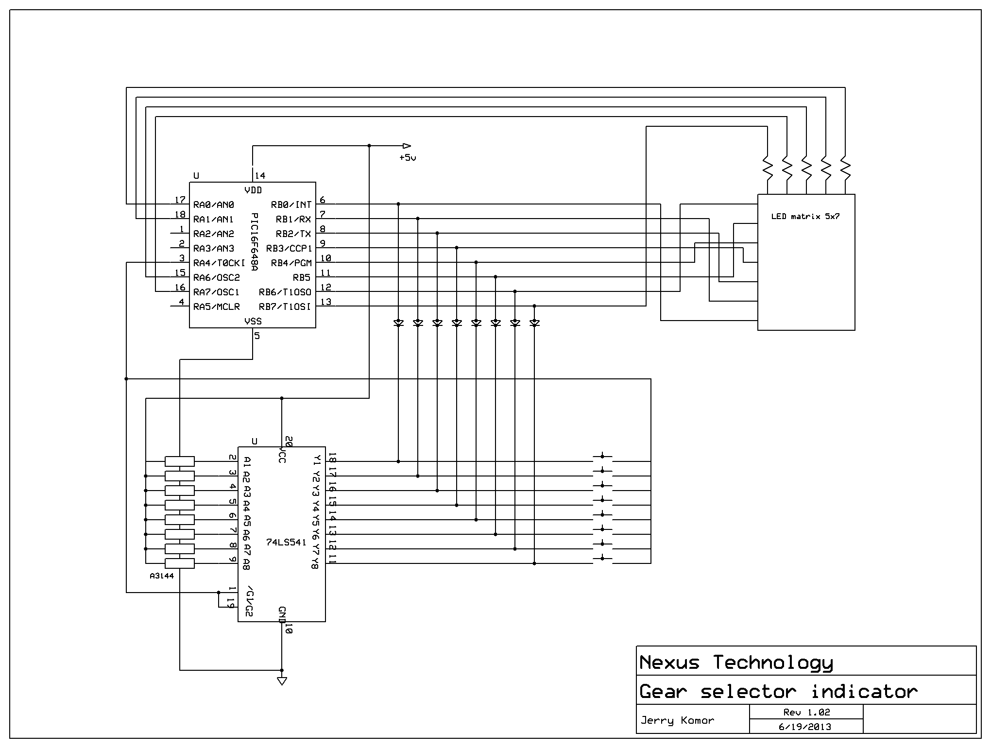
Gear Selector Indicator We are pleased to offer this stripped down version of a part of electrical system I’m developing for my car. In essence it is a stand alone gear display that will indicate which gear I'm in on 5x7 LED matrix. Full version has support of options like selecting if its manual or automatic transmission, dual color option and communication bus to other systems. Where as this one does not have those options. All characters / symbols can be made custom by altering the character lookup table within the program. As such it still can be used with either manual or automatic transmissions Main design feature of it was to make it as least component dependant and
simple. There are 2 main components to the circuit
Since the processor has only 18 pins 2 of which are used for power and
another 12 are used to drive the LED display that leaves only 4 pins that could
be possibly used to sense which gear you are in. Basic layout seen in above
schematic
illustrates of how things are laid out. There are 2 possible ways to setup gear
sensing and both are in the schematic. One is to use switches which would
be activated by the gear stick, problem with that is that the switches have to
be precisely mounted to activate the switch. Other option is to use hall effect
sensors which are triggered by a small magnet mounted on the gear stick. This is
probably better as the hall sensors just need to be in close proximity to the
magnet to be tripped.. Disadvantage of it is that it requires some sort of
buffer as the hall sensors do not have output control/enable pin hence we use
the extra 74hc541 is a line buffer that we can put into hi impedance vi control
signal from the processor. Software operation To create a characters is very easy and to understand and is illustrated in following example.
In this example we are generating letter N and R. We are interested in only 5 least significant bits of the byte and need 7 bytes for each character. Each row is a byte stored in processors eeprom as 7 byte string. Hence we have 11 19 15 15 13 11 11 in the string for letter N
and 1e 11 11 1e 14 12 11 in this example for letter R. Though constrained to only 5x7 space the possibilities are limitless of what it can be displayed
So grab your self some parts and code found here and build your self a custom gear indicator.
Bill of materials 1 Microchip PIC processor PIC16f627 or PIC16f628 or
PIC16f648
|
|
| All content is copyrighted 2014 | |