|
Welcome to myChimaera.com |
||
|
|
||
|
Interior fuse box Work had started on the part, it is progressing and will be updating content on this page often, please come back soon and often for updates. We like to use as many OE parts as possible and not re-inventing new wheel if
it is not necessary. However at some time there will be need to at least
modify it to either fit the need or because you like to have it make it your own
version of it. |
||
|
Fisrt impression of the BCM is that its fairly complex and has number of
functions - internal interface to relays, fuses and sensors - external 2 connectors for various sensors and interface to stalk switches - relay control in the fuse box - key identification (security) - door locks - turn signal controls - light controls - interior light control - CAN (single wire CAN 33Kb) low speed interface to alarm and other modules with in the car - acts as bridge interface to instrument cluster by sending CAN messages reducing connections to the cluster. To replicate the module will require knowledge of all connections and understanding of specific CAN messages which are readily available through number of publications. |
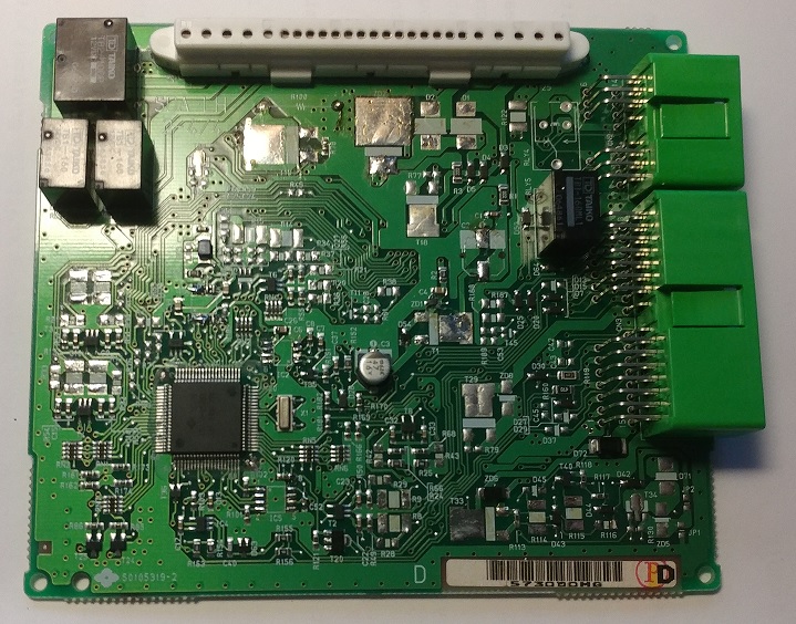 BCM printed circuit board |
|
|
First step is to revere engineer interconnections between all of the connectors,
fuses and replays. by opening the case the case, back side reveals BCM PCB plugged into 25 pin internal connector on top of a sand witched 7 layer heavy trace layered assembly that routs various wiring pathways between all the connectors relays and fuses. With the assistance of CAD program, all connection points where drawn up and using a multi meter each connection point was carefully traced and marked with appropriate signal name. By putting a mouse pointer on particular pin it is very easy identifiable of where that particular interconnection is split and goes to. Further to assist labels where added on each connector pin of where it is going to and being used for. Respectfully each wire on harness was also labeled for easy identification later on when modifying each harness will be required.
|
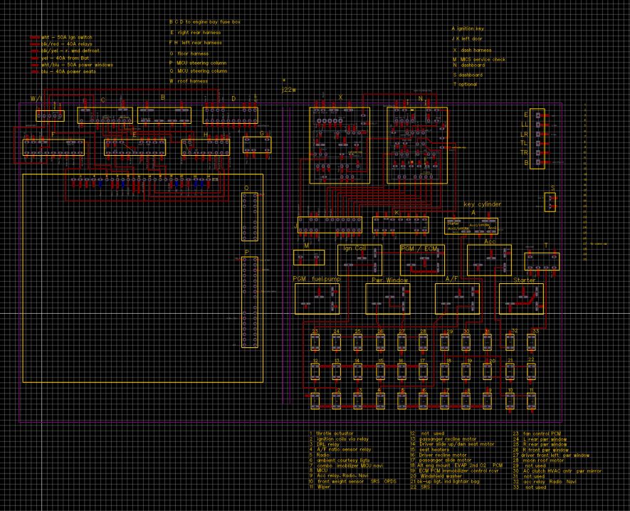 Fuse block connection map |
|
|
With all of the interconnections decoded, its time to make the new BCM
control board. Connectors on the board can not move as they are need to follow
internal pins and same will apply to the external connectors P & Q will
change some locations for some of the pins as that the harnesses will be more be
more direct connection between the fuse box and rest of the sensors with in the
car. Will also keep window regulator control relays along with all the other functions of the BCM. Howerver will use a newer processor in place of the original Motorola one. With that in mind a new PCB was created in same size with internal connector pins and mounting holes as the OE. CAD connectors profiles for P & Q where created and placed in original locations. |
||
| Firmware ?? | ||
| All content is copyrighted 2014 | ||